In the previous part
In Part 4 I selected C3, C4, and Cz as the smallest practical montage for my motor imagery experiments. The analysis worked on a public dataset, but the recorder itself still did not exist. Before putting electrodes over the motor cortex, I had to power the ADS1299, communicate with it, and verify that the complete acquisition path could record any biological signal from my head.
Repurposing the evaluation board
What I bought was not a bare ADS1299 chip on a simple breakout board. It was a Texas Instruments prototype system made for evaluating and debugging the chip. The system came in 2 parts: a daughterboard containing the ADS1299 and its analog circuitry, and a motherboard responsible for powering and controlling it and passing the data to the supplied Texas Instruments software.
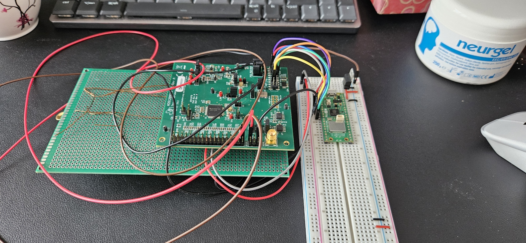
That was enough to inspect the chip, but it was not designed to become part of my own real-time application. The useful hardware was tied to the evaluation motherboard and proprietary software, while I needed continuous raw samples inside a signal-processing pipeline that I controlled. I therefore disconnected the Texas Instruments motherboard, kept the daughterboard, and bought a Raspberry Pi Pico W to take over its control and data-acquisition functions.
This changed the evaluation board into a useful starting point, but it also removed the infrastructure that made it work. The Pico now had to initialize the ADS1299, configure its registers, start the conversion, read every sample, and send the data to my computer. I also had to provide all of the required power rails myself.
Supplying my own power
The first major problem was power delivery. The daughterboard expected specific supply rails which I could not obtain from the Pico itself, and powering an EEG recorder from a computer would reintroduce mains interference into a circuit measuring signals in microvolts.
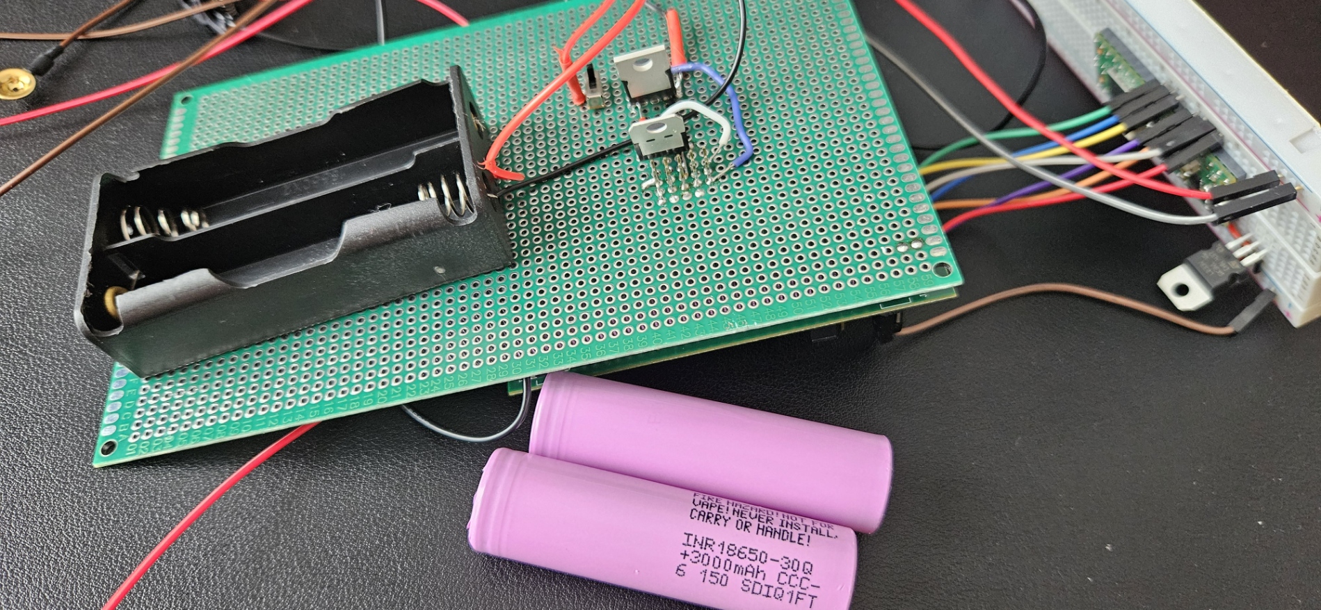
I used 2 lithium-ion batteries, each providing approximately 3.5 V. Connected in series, they gave me approximately 7 V, which I then reduced using 3 low-dropout regulators (LDOs). One regulator produced 5 V and another produced 3.3 V for the ADS1299 daughterboard. The third regulator provided a separate 3.3 V rail for the Pico.
I soldered the batteries, regulators, and power connections onto perfboard. This replaced a large part of the loose breadboard wiring with shorter and more stable connections, reducing another possible source of noise. The Pico remained on a breadboard, which was less elegant but made it much easier to change the digital connections while I was still bringing up the interface.
I also needed wireless communication. A recorder attached to my head had to remain battery-powered and disconnected from the mains-powered computer during a recording. Wi-Fi removed the USB power and data cable, and with it a direct path through which 50 Hz interference from the power system had been entering the recording. The Pico could collect the samples and transmit them while the complete subject-connected circuit remained on batteries.
Writing the interface
The next problem was software. The Pico was replacing the original motherboard, but it did not have a ready-made protocol for controlling this daughterboard. I had to implement my own control and data-acquisition procedure around its SPI interface: check that the ADS1299 responded, write the required registers, start continuous conversion, and reconstruct the returned samples.
Learning every detail of the ADS1299 register interface was not the purpose of this project. My objective was to work with EEG signal processing and motor imagery, not to become good at remembering the startup sequence of one analog front-end chip. I used an LLM to help turn the datasheet into an exact implementation procedure, then checked the result against the device response and the data coming from the board. Once the chip could be configured reliably and produced a continuous stream, the low-level interface had done its job.
This was an appropriate use of the tool for me: it accelerated a necessary engineering detour without changing the part of the project I actually wanted to investigate. I still had to assemble the circuit, debug the communication, and verify that the resulting samples represented a real input rather than a plausible-looking software error.
The first signal
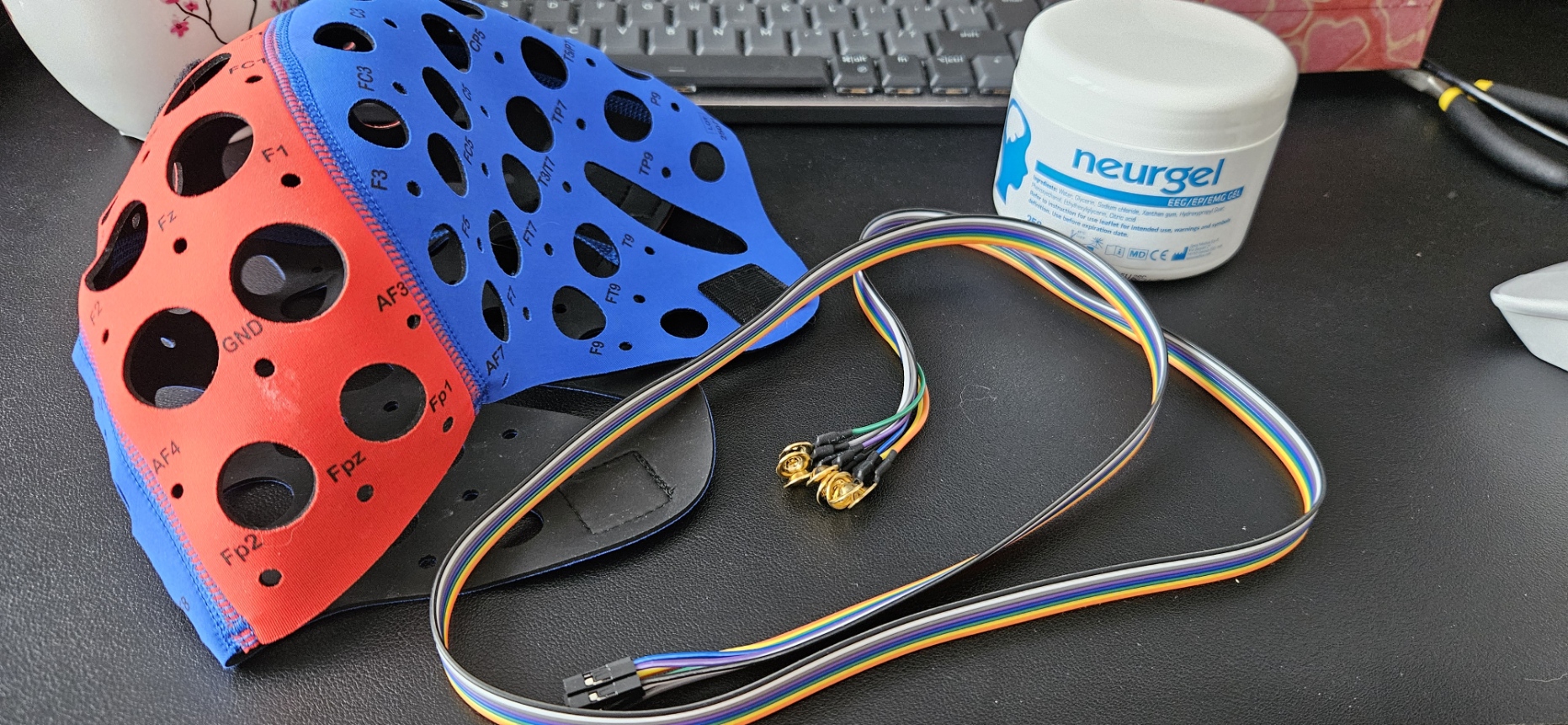
For the first proof of concept I did not immediately use the C3/C4/Cz montage selected in Part 4. I bought wet electrodes, conductive gel, and an EEG cap marked according to the international 10-20 system, but started with the simplest recording that could show whether the complete chain worked. I placed the recording electrode at Fp1, the reference electrode on my earlobe, and the bias electrode at Fpz.
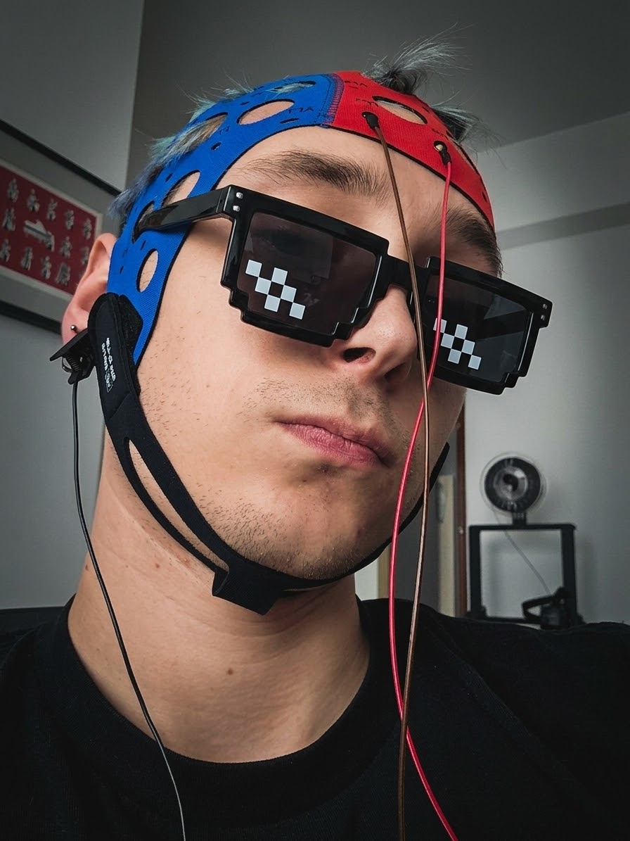
That setup produced my first signal from the custom recorder. It was very noisy, so I preserved the raw recording and applied an initial filter to a copy of the data. During a 12-second test I blinked 6 times. The filtered Fp1 signal showed 6 large deflections at the corresponding moments, which made the event easy to identify in the recording.
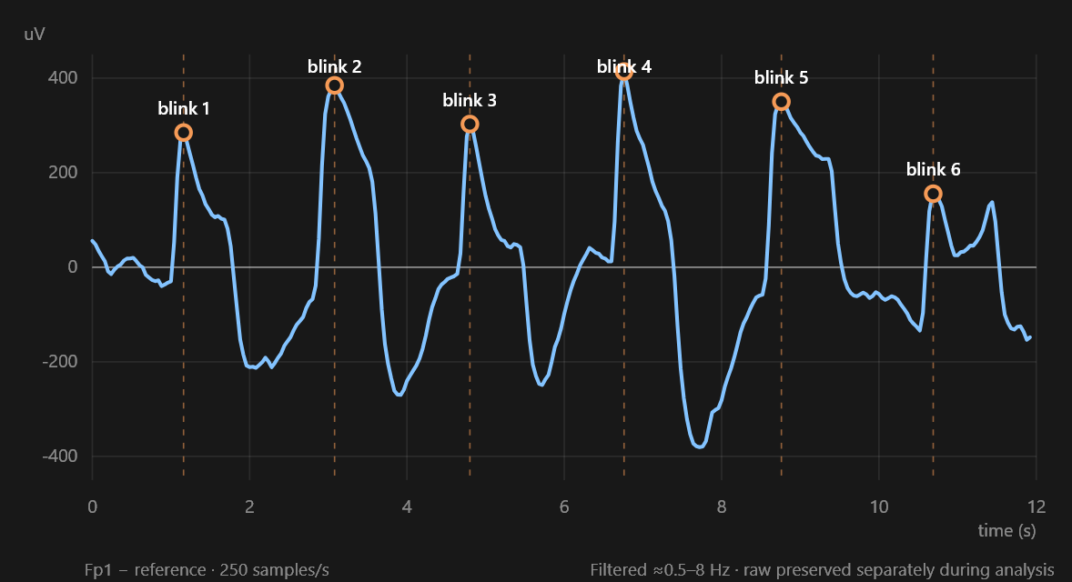
The peaks were eye-blink artifacts, not EEG activity. This was exactly why they were useful for the first test: a blink produces a large and recognizable electrical change near Fp1. Recovering those events showed that the batteries, regulators, ADS1299, Pico, wireless link, electrodes, and software were working together well enough to collect a real signal from my head and preserve information inside it.
That was enough for the proof of concept, but it did not yet show that the recorder could capture useful EEG. The next problem was to reduce the remaining noise and move the recording electrodes from the convenient frontal test position to C3, C4, and Cz over the motor cortex.